A
lightweight cross-polarisation (X-P) version of the WOS LFA.
Although I have been reasonably successful with my attempts at 6M EME, I still suffer from significant local noise on my horizon as discussed elsewhere putting me at a disadvantage compared to those stations located in the countryside. Any one who has attempted 6M EME will also know that there is considerable and rapid polarisation changes which can considerably attenuate already exceedingly weak reflections from the moon. Note: Polarisation can change many times within a JT65 period so this is why I stopped building a mechanical solution to change the polarisation as it probably would not help improve reception.
I needed a winter project so I thought I would have a go at building a cross-polarisation version of the 'WOS LFA' and tray and see whether I could benefit from the use of Adaptive Polarisation using a two-receiver SDR.
This page is dedicated to the build of the x-p antennas while this page will talk about the electronics.
Step number one was to get Justin, G0KSC to design me a new antenna based on an x-p design. I had one additional requirement - to make it lighter in weight. The WOS LFA is a well built antenna but it is quite heavy so adding on an extra set of element would really make it too heavy for my bay configuration. So I made the following changes to lighten it:
- Use 3/8" aluminium tube rather than 1/2" tube for the elements - except for the loop. This is lighter and obviates the need for all the hose clamps except on the loops.
- Use 'rivnuts' to bolt the Staff clamps to the boom which means shorter and lighter screws can be used.
According to my calculations, this will make the x-p version only a couple of pounds heavier than the standard WOS LFA. Of course, it will not be as robust but I do not get winds that are too strong at this location - so fingers crossed that this does not change!
The weight of the original WOS-LFA is 24.56lbs (11.14kG) and the weight of the new lightweight X-P version is 25.36lbs (11.5kG), so the new version is only 1lb heavier than the original! Objective achieved!
The WOS LFA X-P design
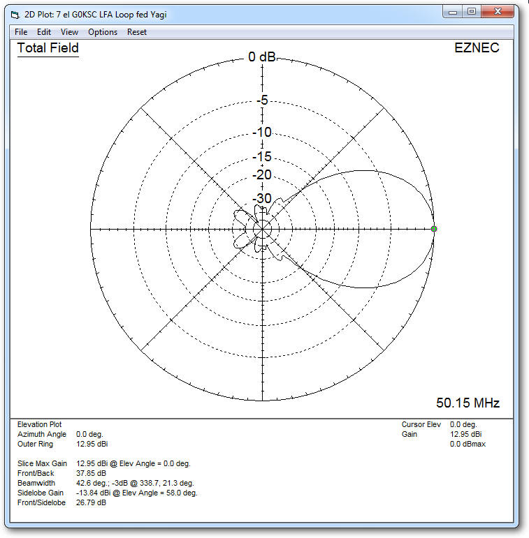
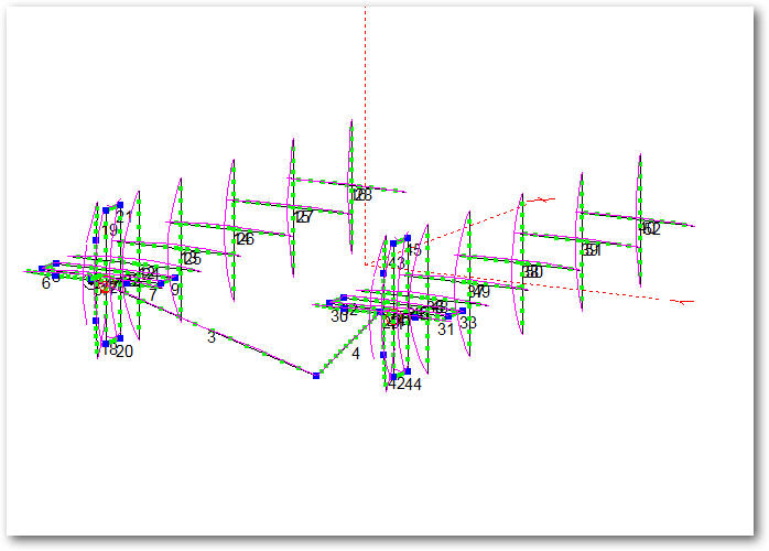
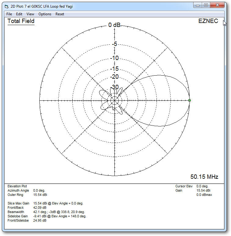
The EZNEC design can be seen below - the h and v elements are offset by 110mm with the v-elements in the front. A single antenna has a forward gain of 12.95dBi and front/back ratio of 37.85dBs. The bayed version spaced at 6M has a forward gain of 15.54dBi and front/back ration of 42dBi.
The EZNEC model of the Lightweight x-p WOS LFA antenna
Single X-P WOS LFA azimuth plot
The azimuth plot shows similar performance to the WOS LFA with very highly suppressed secondary lobes.
Bayed X-P WOS LFA @ 6 metres
The EZNEC plot below shows the performance of an x-p bay using these antennas. With an optimum spacing of 6 meters, the forward gain is 15.54dB with the same good suppression of secondary lobes. Spacing at 6.5 meters does add around 0.2dB of forward gain but it was not thought that the mechanical challenges brought about by the additional spacing of 0.5 meters was worth the effort.
I was concerned about the impact of the feed cables so I modelled them. Fortunately, they do not seem to impact the arrays pattern.
A close up of the feed cable taken out of the back of the horizontal antenna. I did not really want to take the feed cable through the boom to exit out the back as prefer to be able to inspect the cable from time to time. The cable are elements 1 and 4.
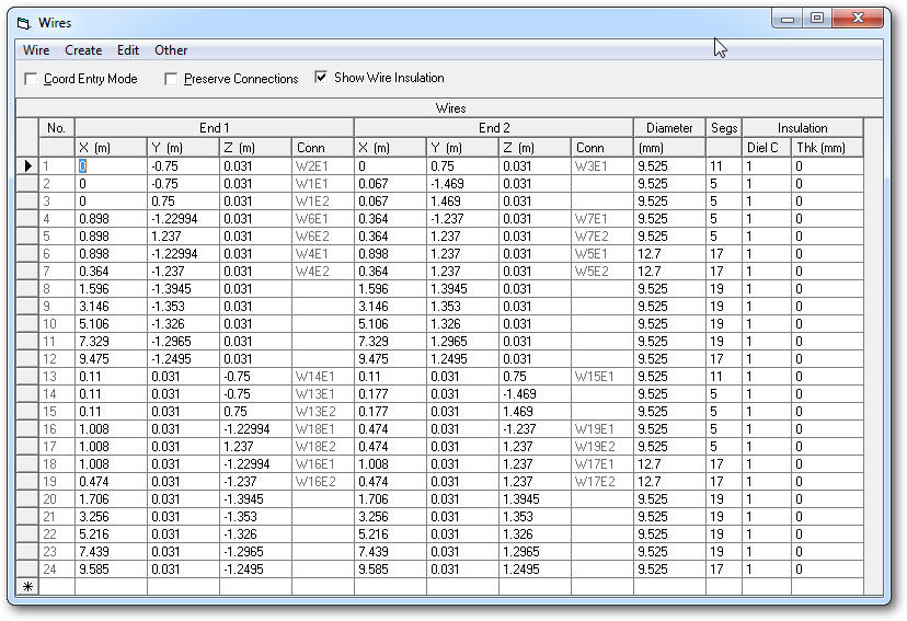
EZNEC wire sizes.
These are the dimensions of the X-P WOS LFA antenna.
Reflector dimensions
As the ends of the reflector are bent forward by 67mm, the physical length of the reflector needs to be increased by a small amount to compensate. Using a calculation based on a right-angle triangle ( one side = 719mm and the other 67mm) it can be found that it needs to be extended by 3mm on each end.