An alternative to the 6M7JHV antenna for 6m / 50MHz
The specification
It may sound easy to compare the specifications of the two antennas but you would, surprisingly, be wrong. The 6M7JHV specifications are in the form of a 'simplified' marketing specification, whereas, G0KSC is concerned with providing hard verifiable engineering specifications which is very welcome. However, let's have a go with the appropriate notes of explanation from Justin, G0KSC.
| 6M7JHV (Spec) | LFA2 | |
| Frequency | 50.0 - 50.4MHz (1) | 50 ->50.6MHz @ <1.1:1 |
| Gain | 10.9 dBd (3) | 10.8dBd @ 50.150MHz |
| Front to back | 25 dB (3) | 30.74 dB @ 50.150MHz |
| Front side lobe E-plane | - | -30.4 dB |
| Beam width E-Plane | E=40� | 43� @ -3 dB |
| Beam width H-Plane | H=42� | 49.8� @ -3 dB |
| Feed Impedance | 50 Ohms | 50 Ohms |
| VSWR | 1.2:1 (2) | <1.2:1 (49.95 - 50.75MHz) (4) |
| Power Handling | 1.5 KW | Limited only by coax rating (5) |
| Match Type | 'T' Match | None (direct 50 Ohm feed) |
| Balun | 4:1 Coaxial | G0KSC 1:1 Antenna Balun |
| Boom Length / Dia. | 30' 8" / 1-1/2" O.D | 31' 5" 1-1/2" sqr. tube |
| Element Type | 3/8" tube | 1/2" / 3/8 " tube |
| Mast Size | 2" | 2" |
| Wind Area / Survival | 2.5 sq ft / 85 MPH | 112 MPH (6) |
| Weight | 17 Lb | ? |
(1) (2) What criteria actually determines this quoted bandwidth? One has to assume it's based on the bandwidth where the VSWR is less than the quoted VSWR of 1.2:1 i.e. an 'SWR bandwidth'. My 6M7JHV has a VSWR of less than 1.2:1 over a bandwidth of 220kHz with a minimum peak of VSWR of 1.17:1. Whereas, the LFA 2 has a bandwidth of over 700kHz quoted on the same basis.
(3) It look likes M2 quote highest gain and highest F/B ratio, regardless of where this appears in the provided bandwidth range. To quote Justin, G0KSC:
"For example, like the bandwidth/SWR issue, M2 do not make it clear where in the bandwidth these figures appear. In most cases, best F/B is obtained at the bottom of an antenna's bandwidth while best gain is achieve towards the top end. Therefore maximum gain could be around 50.4Mhz. This is another trait of narrow band Yagis; performance is not maintained across the band as they are with the LFA."
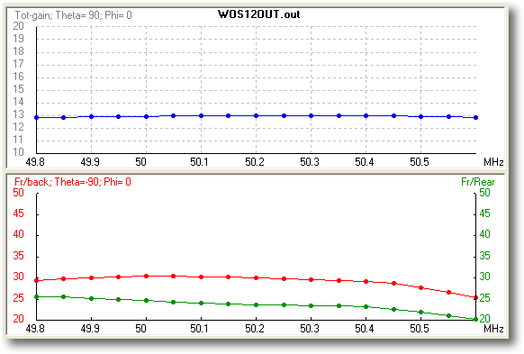
With the LFA design, the f/b and gain are flat across the complete the required bandwidth of 50 to 50.4MHz

Front to back of the LFA over the designed frequency range (7)
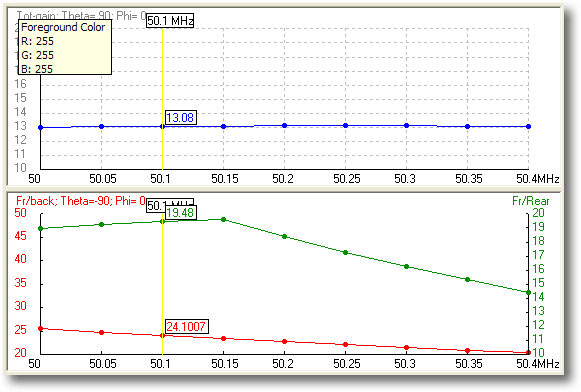
Whereas, the 6M7JHV f/b drops away as the frequency rises.

Front to back of the 6M7JHV over the designed frequency range (7)
(4) Our specification for the required bandwidth of the antenna was 50 - 50.4MHz.
(5) The 6M7JHV uses a 4:1 T-match to bring its impedance up from 16 Ohm to 50 Ohm. The LFA does not. If any part of the antenna is most likely to fail from high RF power it's most likely to be the matching assembly. To quote Justin G0KSC:
"The LFA does not have any matching assembly. All Yagis require a balun (Balanced to Unbalanced transformer) at the feed point to prevent common mode currents on the feed line. This is what the antenna balun does. To this end, where as the T match has some very high currents and voltages floating around limiting it's power handling, the LFA does not".
So the power the antenna is probably only limited by the capability of the feed cable. Other LFAs have been tried with 3KW PEP and 2KW key down with no problem.
(6) To quote Justin, G0KSC:
"I have calculated wind survival within Yagi Stress. The boom handling is 112MPH while the elements can withstand 175MPH. Therefore, the wind survival can be quoted as 112MPH."
(7) As modelled by G0KSC in EZNEC Pro/4.