An alternative to the 6M7JHV antenna for 6m / 50MHz
Power divider / splitter
As an alternative to a phasing harness, it's possible to build a 2-way splitter which is a more precise way of matching two 50 Ohm antennas. These can be bought commercially.
50 Ohm two-port power divider
Credit: W7CQ and ST October 1973
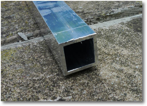
Justin, G0KSC identified the sizes of box section and tubing to use but I thought it worthwhile checking the size suggestions:
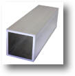
1 1/4" by 10 gauge = 31.75 mm outside dimensions with 3.2512 mm thick walls.
Therefore, the inside size in inches = 0.994"
Available from Aluminium Warehouse.
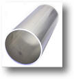 The inside tube is 15mm copper water pipe.
The diameter in inches = .5905"
Impedance of the quarter wave transformer:
Calculate the required impedance of the quarter wave transformer, Zo
![]()
Z1 = Coaxial cable impedance = 50 Ohm
Z2 = Antenna's combined Impedance = 2 ports = 50 /2 = 25 Ohm.
![]() = 35.355 Ohm
= 35.355 Ohm
Impedance of a square tube with round centre tube:
Now calculate the impedance, Zo, of square tubing with round centre tube:
D = inside dimensions of square tube = 0.994" , d = outside diameter of round centre tube = 0.5905".
 = 35.824 Ohms
This equates to only an error of 1.3% from the ideal to the practical which is pretty good.
Length of the transformer:
The length of the transformer is a free space quarter wave of 50.110MHz:
Length = 300 / (50.110 *4) = 1496mm (from N-type pin to pin).
Making the splitter
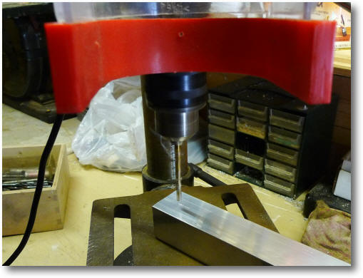
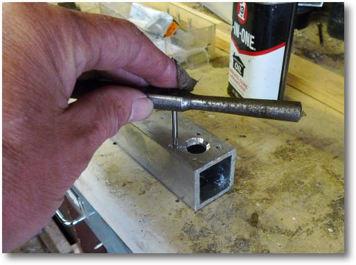
Mark out the 1 1/4" tube for the position of the N-type sockets.
Drill the holes for the N-type sockets.
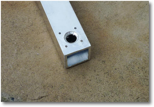
A small rebate is required for the step on the back side of the scockets.
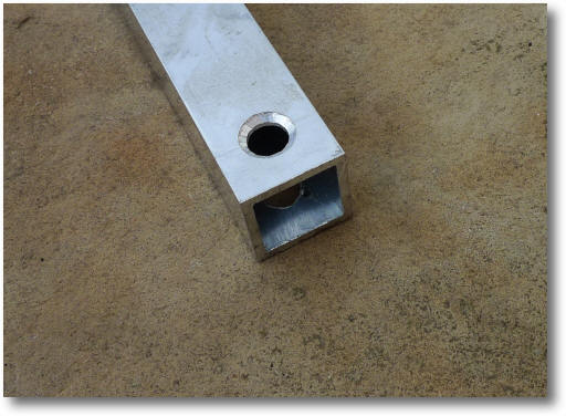
Drill and tap all 12 holes for the M3 socket retaining screws.
The finished holes.
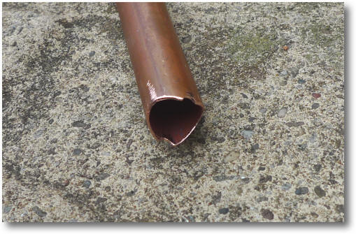
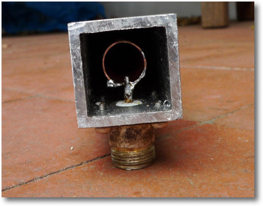
Cut the 15mm copper tube and and file the three slots that will align with the N-type sockets.
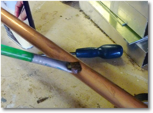
After cleaning the copper pip, varnish it (but not where you have to solder!).
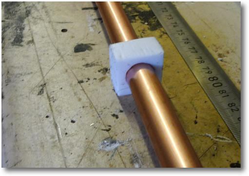
To hold the tube steady, make a small PTFE spacer that will push fit over the 15mm copper pipe and push to the centre of the pipe.
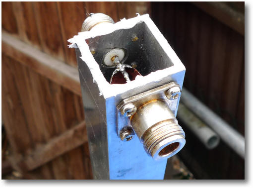
Using a large soldering iron, solder the output end of the copper pipe to the N-type plugs.
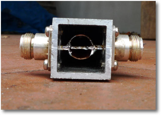
Solder the input end.
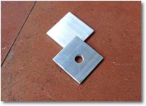
Cut two pieces that will form the end caps of the divider. The hole in the bottom is let out any condensation that may form inside - this should therefore be placed at the bottom!
Apply bathroom sealer to the end of the tube.
Place the end cap on the divider and press home.
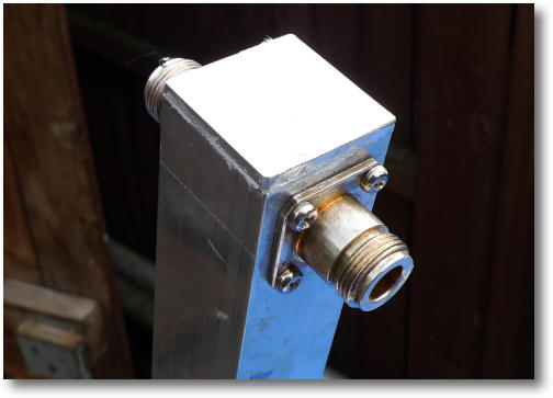
Tape over the end to hold the cap in place. More waterproofing can be done after the 50 Ohm coaxial cables have been connected.
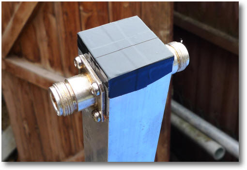
The complete 50Mhz divider.
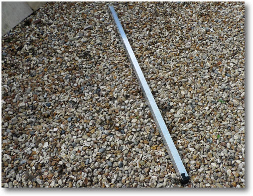
The completed power divider / splitter
The divider is now installed and working on the tower - to see the results go here. It worked first time and I'm very pleased with the results.