An alternative to the 6M7JHV antenna for 6m / 50MHz
Why replace our 6M7JHVs?
Chris, G3WOS and Paul, G4CCZ have been using a stack of M2 6M7JHV high performance 7-element beams made by M2 Antennas of California for many years. My (G3WOS) stack of 6M7JHVs has served me well for the last twelve years and are still in good condition (except for one point that I'll touch on later). So why would Paul, G4CCZ, and I want to change them after all these years? Especially as it still seems to be the mostly widely selected 7-element antenna today for traditional DXing and for stacking for EME operation.
 |
 |
|
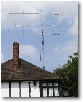
The old 6M7JHV stack at G3WOS |
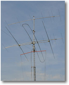
The old 6M7JHV stack at G4CCZ |
Why would we want to replace them? Well, for a number of reasons I think. Let's look at them.
Improved pattern and performance
The following azimuth plot was included on the assembly instructions of the 6M7JHV when I originally bought the antennas. The plot looks unusual as it shows both E- and H-plane free space plots on the same graph.
The 6M7JHV azimuth plot as found in their assembly instructions
A free space YO plot of the 6M7JHV has also been created by Jay, K0GU.
We felt that this azimuth pattern could be improved upon with the advent of new highly innovative designs on the market such as Justin, G0KSC's LFA2 designs.
Most of us live in highly built up areas and the biggest problem that limits our ability to work terrestrial DX or EME is local noise. Anything that can be done to reduce it would be worth its weight in gold. Justin's designs promise just that.
The impact of a high Q antenna design
Below is a plot of my 6M7JHV antenna at the top of my 18M tower. First let me say that my configuration is probably highly suboptimal as the antennas are only 5M apart, which is less that M3 stacking distance and I a have a 7-element 70MHz beam in between them. However, I am not alone in seeing the issues described below.
Narrow bandwidth:
When the antenna was designed in the mid 1990s the main interest of 6m DXers was the performance of the antenna at 50.110MHz which was the centre of action for DX. IF the antenna worked well there, everything was good in the world. The overall bandwidth with an acceptable SWR could be quite narrow without any problems. As can be seen above, the bandwidth of the 6M7JHV is quite narrow with not a particularly low SWR at resonance.
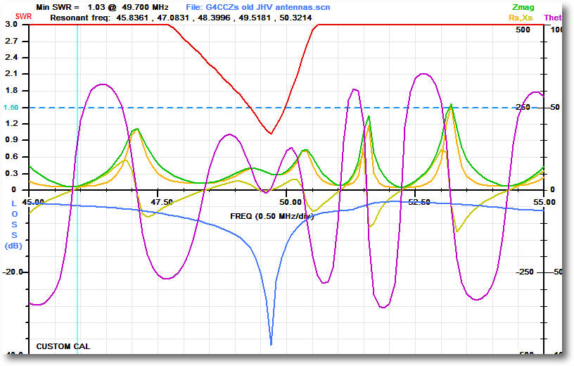
Such a high Q design now causes problems. Firstly, I found that closely stacking a pair of 6M7JHVs substantially lowered the resonant frequency below the bottom of the band. The only way this could be corrected was by shaving 30mm off the end of each driven element and this moved the resonant point back up to 50.100MHz. Interestingly, placing the 70MHz 7-element beam between the stacked antennas moved it down again to 50.050MHZ. The 6M7JHV is highly sensitive to its surroundings and even the SWRs are different between the top and the bottom antenna. Until modified, my pair always resonated below 50MHz as can be seen in the AIM analyser plot below.
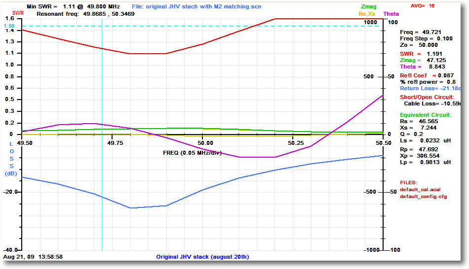
An AIM analyser plot of the 6M7JHV stack on G3WOS's tower using
the standard M2 T-match. (Thanks to G3ZSS for the loan of the AIM analyser)
The graph below shows Paul G4CCZ's stack which exhibited similar problems to mine.
An AIM analyser plot of the 6M7JHV stack on G4CCZ's tower using
the standard M2 T-match.
Affected by nearby objects:
Living in the UK as I do, I have to suffer living in a house with a small garden and nearby neighbours. It has always amazed me how the SWR was affected by my neighbour's chimney and TV aerials! When ever I tuned my beams in that direction the SWR noticeably deteriorated.
SWR affected by rain
I have heard that the SWR of the 6M7JHV is affected by rain although I've never looked at that issue myself.
The advent of digital communication and EME:
Though the 6M7JHV sits comfortably in the frequency trough it was designed for, JT6M and JT65 EME QSOs take place at a much higher frequencies - say between 50.190 and 50. 260MHZ. The 6M7JHV is really uncomfortable at these higher frequencies and exhibits a much higher SWR - for me as much as 1:1.4.
Operating EME with JT65 demands high transmit power and high duty cycle. This combo is an amplifier killer which has been amply demonstrated in the last few years with numerous amplifiers used for EME going up in smoke around the world. Amplifier stress through over-heating is bad enough without adding to it with a high SWR. Justin's LFA design promises high bandwidth which could be an answer to this bandwidth problem.
The 6M7JHV uses a T-match:
As I mentioned above, the 6M7JHV antennas have lasted very well at G3WOS's QTH. A renovation last year showed little damage or corroding after 12 years in the air, although I have to say that I am very sheltered at my QTH. I have to say that I've got quite attached to them in that time.
However, there is one key part of the design that is sub-optimal in design and that is the T-match and its shorting bars. The shorting bars are tightened on the driven element and matching rod using tiny grub screws. After a few years in the open air these corrode and I defy anyone to be able to get them out. I ended up sawing them off and making some new ones that used hex head screws as can be seen in the photo below.
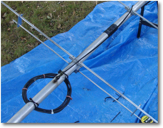
The rebuilt 6M7JHV shorting bars
In 2009 I experimented using a hairpin match ( with adjustable elements) rather the supplied T-match on the 6M7JHV and fed with a Pawsey stub as described by Justin, G0KSC. I was interested in seeing if I could improve the SWR (which never seemed to be better than 1.1:1 and rose alarmingly to 1.4:1 around 50.20MHZ) and get it to resonate in the band, rather than below it.
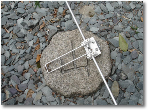
A hairpin loop matched driven element for the 6M7JHV
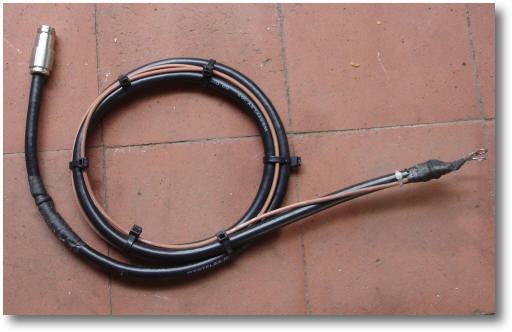
The Pawsey stub balun
It was while I was experimenting with the hairpin match and the adjustable elements that I discovered that cutting 30mm off each side of the driven element brought the resonance point up to 50.100MHz.
To be clear -30mm brought the 6M7JHVs back to resonance on 50.110Mhz whether using the M2 or the Pawsey balun with a hairpin match.
As can be seen in the AIM plot below, I was somewhat successful:
- Resonance was moved to 50.100MHz
- The SWR at resonance was mildly improved.
- The SWR at 50.200MHz was reduced to 1.4:1
- Return loss marginally improved
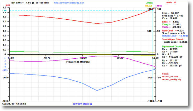
The 6m7JHV, with hairpin matching, 30mm chopped each end of the
driven element and using a Pawsey balun.
The hairpin and stub worked very well, but in the end I went back to the M2 T-match as I was concerned that the new matching assembly may have a negative impact on the performance of the antenna though I had no proof that was the case. I do know of other UK hams that have successfully taken this approach on M2 antennas - Neil, G0JHC being one.