
The Case of the Cardboard Mock-up
I bet most of you are like me? When a starting a new project you immediately go out and buy a chassis and immediately start hacking holes. The next thing that is heard is "whoops" (or more likely !"�$&^ or its non-English equivalent!). This usually means a few holes that need patching up or filled in.
This design methodology was just not appropriate in this case (sorry for the pun) as everything needed to fit closely together as I had little room. I therefore decided to do something I have NEVER done before and build a cardboard mock-up! And boy, am I glad I did! Indeed, fitting the components together was a bit like a 3D puzzle and this actually determined the minimum size of the case I could use. Fortunately, everything fitted!
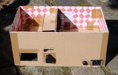
The cardboard mock-up of the case
Some of the layout goals were:
-
I should be able to take the blower off in transit
-
There should be a minimum of items sticking out of the case (all screws needed to be countersunk) so it could slide into the case.
-
The amplifier was going to be used in tropical locations so the power supply needed to air-cooled as well as the 8877.
-
I needed to be able to open it easily if customs officers wanted to inspect the insides.
-
Nothing could come loose inside - especially the 8877!
From a design perspective, it became clear to me pretty quickly that the floor of the RF deck on the left needed to be higher than the floor of the power supply area on the right. The minimum distance of the RF deck floor from the bottom of the case needed to be 70mm to accommodate the blower hole (the large square hole on the lower right). The height of the power supply supply floor needed to be lower at 50mm to accommodate the the HT capacitor bank board that needed to fit in the top compartment of the PSU, next to the HT transformer inset into the floor. 50mm was also the miniumum height I could use for the control board mounted underneath PSU floor.
As it turned out, I needed to extend the case width to the full 410mm so that these two large components (transformer and HT capacitor board) would fit in side-by-side with an appropriate gap. The depth of the chassis (220mm) was determined by the width of the HT capacitor board.
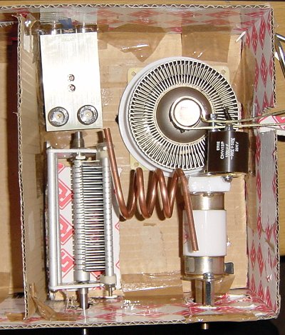
Mock-up of the anode cavity - a snug fit!
After a bit of juggling, I managed to accommodate all the bits in the limited space available. Now, which control board should I use?