
Coming Together - RF Deck!
Here are some photos taken while assembling the RF deck...
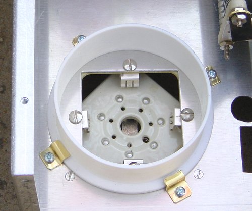
The mounted 8877 base and chimney
The PTFE chimney is held in position with four small hand-made brass brackets. The picture clearly shows the 8877 socket mounted underneath the floor.
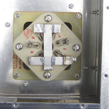
The mounted 8877 base from the underside
The 2 spare pins are for the +5v @ 10A heater supply while the other 5 pins are connected together for the cathode connection.
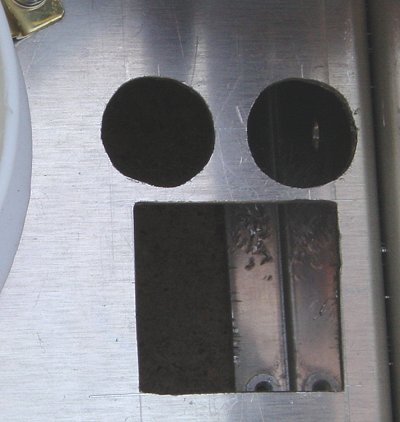
The holes needed to mount the antenna change-over relay
The large hole is for the change-over relay coil to drop through. This can be seen in the photo at the bottom of this page.
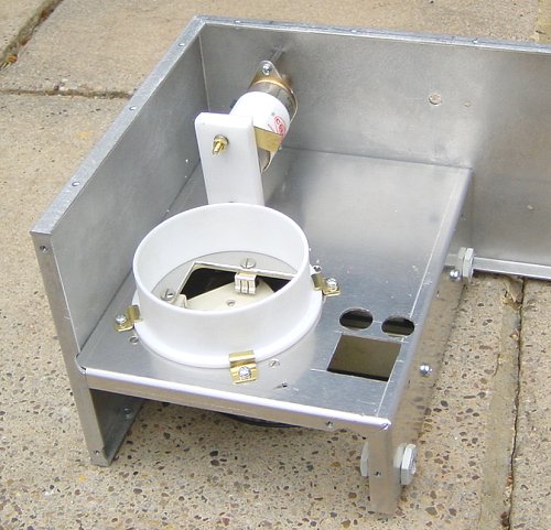
The RF deck chassis
The PSU internal floor has been removed for access. The vacuum variable capacitor is held firmly in position with a piece of 12mm thick PTFE bar screwed to the floor. This will support the 1000pf anode isolating capacitor as well.
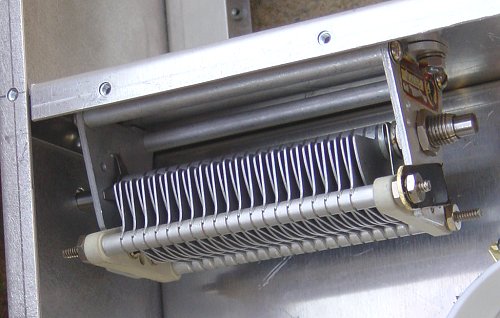
The mounted loading capacitor
The loading capacitor is mounted on the side wall of the anode RF compartment so its spindle horizontally aligned with the vacuum tuning capacitor.
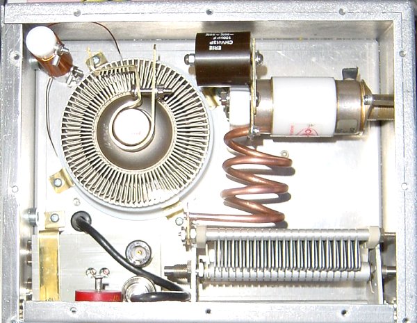
Everything seems to fit in the anode compartment!
The brass and copper bits and pieces will be silvered before final assembly.
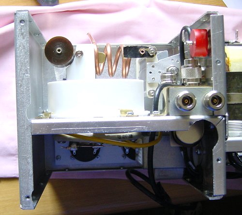
RF deck back view
This picture shows my small screw up - the corner of the floor had to be filed out (just below the relay I/O) so that the socket supplying 240 volts to the fan could be fitted! The red thing above, is the HT feed-through capacitor.
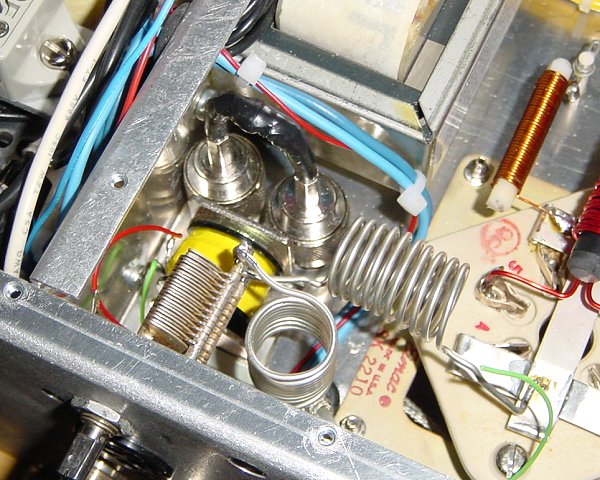
RF input matching circuitry
This picture clearly shows the input matching circuitry, the operating coil of the antenna change-over relay and two of the N-type connector shown shorted together in the receive position. The heater (I replaced this later with one that used 16swg wire to reduce voltage drop) and cathode choke is in the top RHS of the picture.
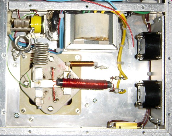
RF deck - cathode side
This picture shows the heater transformer whose +5v output is the yellow wires connected to the heater choke (later replaced with one wound with 16swg wire). The resistor at the bottom right-hand corner is the 2.2k soft-start resistor. Space was so tight in the PSU control compartment it had to be mounted here. There is not much room around the meter board!