Building
the X-P WOS LFAs.
The build is very much the same as building the non-X-P WOS LFA antenna so I will not go into great detail but will only show the differences. Below is what it looks like when built!
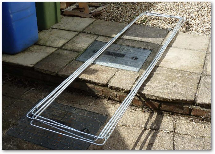
Here are the four loops all ready and assembled:
One of the things I found difficult with the previous LFA build was to cut the slots. This time, I used a circular saw and this worked just fine as can be seen.
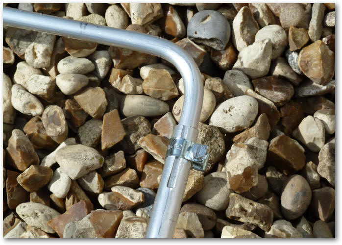
I would also recommend that hose clips that use a screw and nut be used - these seem to work very well compared to other types.
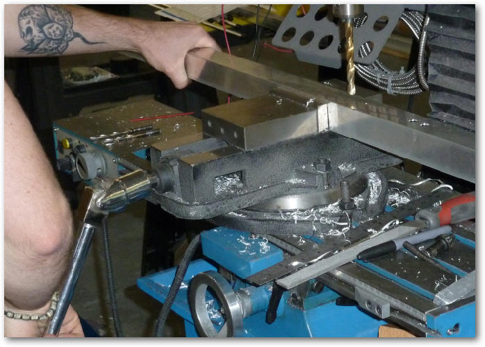
I visited Justin's factory and they kindly drilled all the clamp holes and inserted most of the M6 rivnuts. The picture below shows the milling machine used to drill the 10mm holes for the rivnuts.
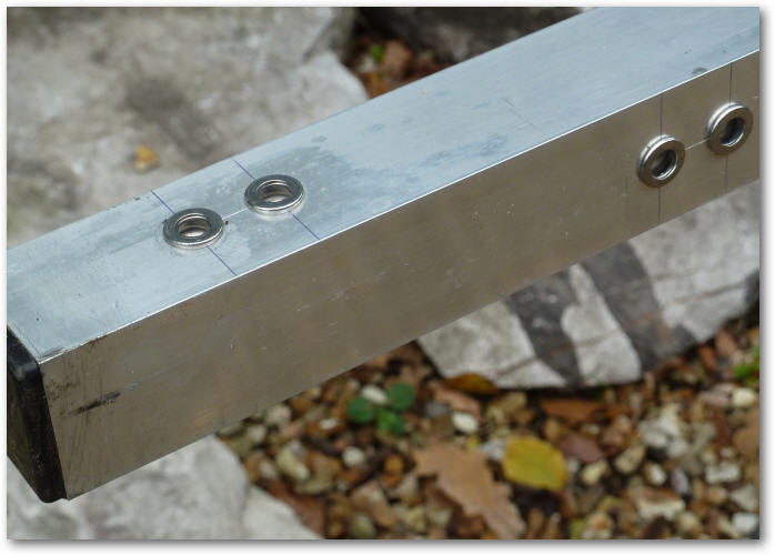
Here are the rivuts in place. Those on the top of the boom are for the horizontal elements and those on the side are for the vertical elements (of course!).
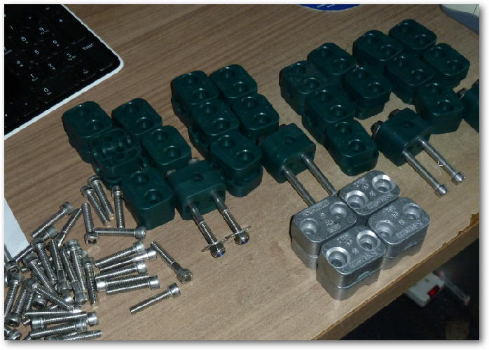
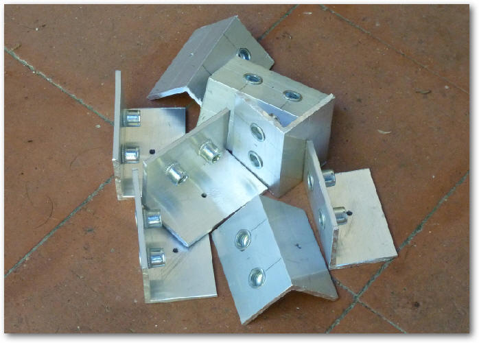
Here are the assortment of Strauuf clamps used to attach the elements to the boom. The aluminium one is used on the front of the loop to ground the middle.
Making the eight driven element brackets...
The driven element brackets completed.
The 3/8" Stauff element clamps. My findings are that using rivnuts means that the elements ar held much more rigidly than using the through-boom bolts I used on my previous build and, of coiurse, are lighter in weight.
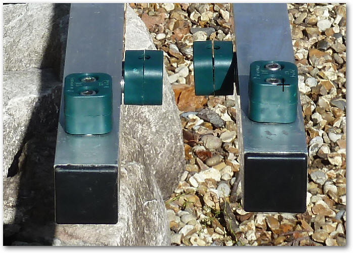
The metal Stauff clamps used to short the loop to the boom.
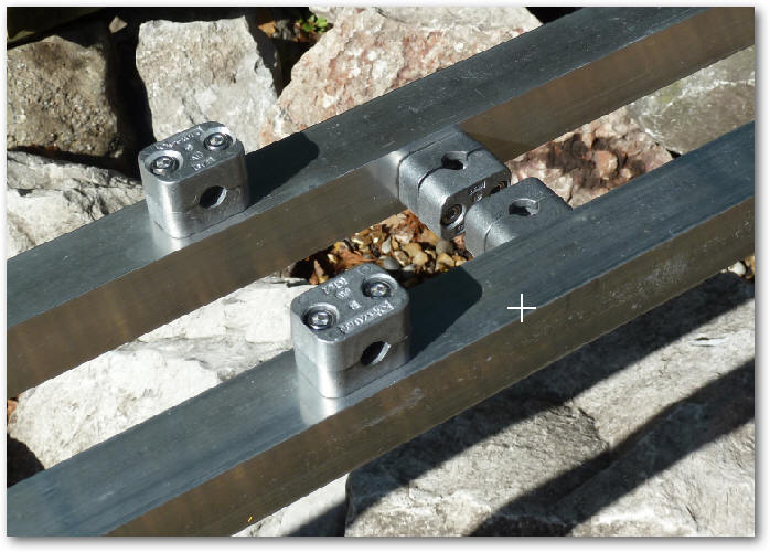
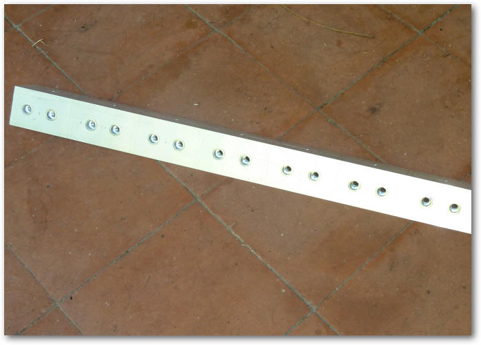
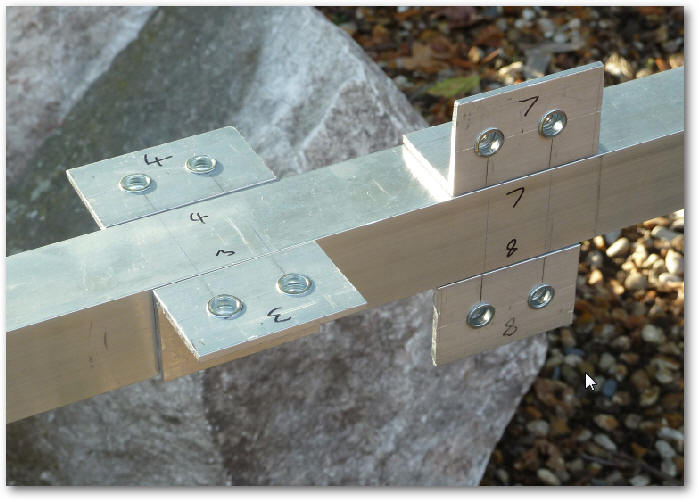
This time I marked the centre position of the clamp on each element thus making it much more easy to centre the elements on the boom.
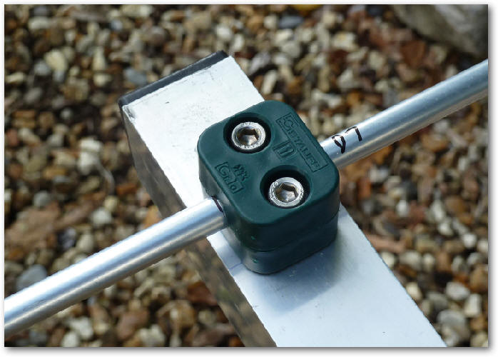
I was a little concerned about using only 3/8" aluminium tube as elements but they seem quite sturdy with little droop. They are not so strong as the previous tapered elements so I'm hoping that I do not have too many fat pigeons perching on them!
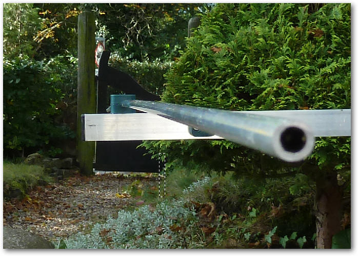
These are the fibreglass tubes I will use for the cross boom - more on this later.
The four mounting brackets that will support the two driven elements (loops).
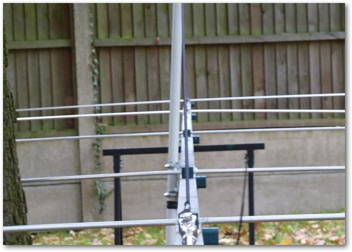
The business end coming together showing the loop and the bent reflector.
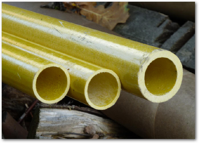
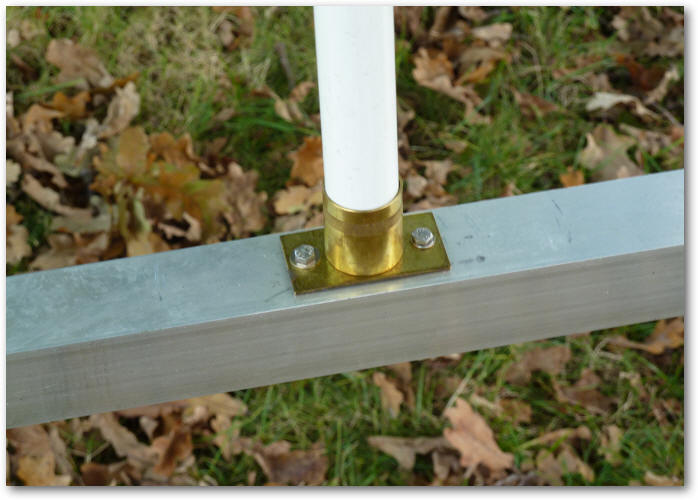
Due to this being an X-P antenna, I am unable to use aluminium tube as the strain relief support so I've had to buy some 1" fibreglass tube. One of the things I was not comfortable with on my previous design was that this strain relief was bolted to the side of the antenna boom making it offset from the boom. This arrangement bowed the antenna slightly. This time I have managed to find some brass towel rail supports that I will bolt on to the top of the antenna thus the weight will be centralised this time.
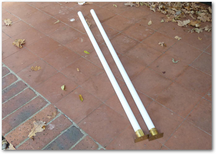
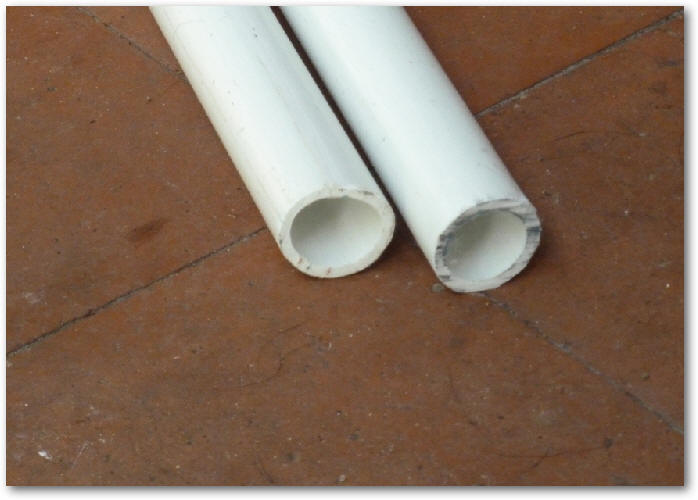
The 1" fibreglass tube.
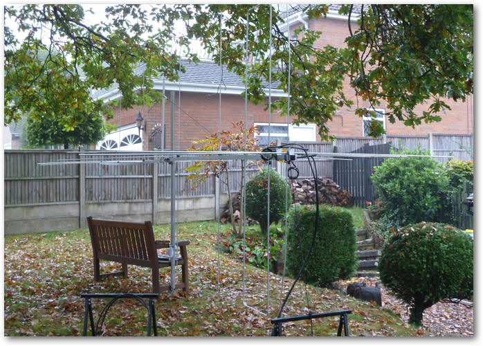
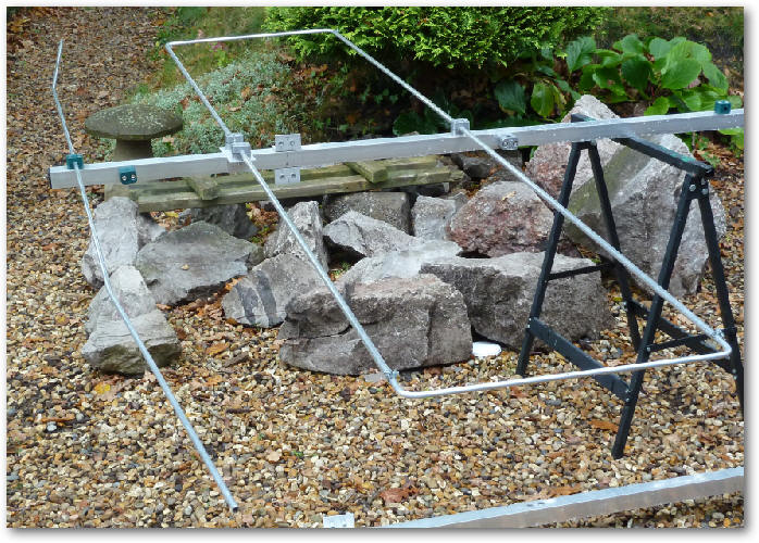
I eventually scrapped the above approach and built a boom bracket as I thought is possible that the support stanchion could flip sideways allowing the antenna to droop. Using an iterative approach (and using two support ropes for the front section) by moving the bottom of the stanchion to ensure it is vertical I managed to create a very straight boom! The secret is to make sure that the stanchion is placed as near to the point of balance a possible.

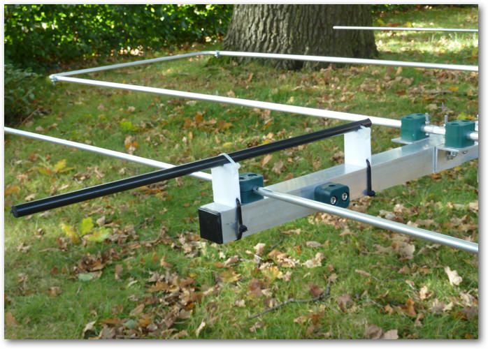
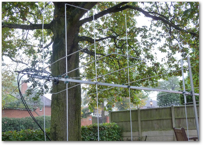
Here are all the 'H' elements mounted on the boom. This only weighs 20.73lbs compared to the 24.56lbs of the original antenna - and this is with all the 'V' element clamps attached!
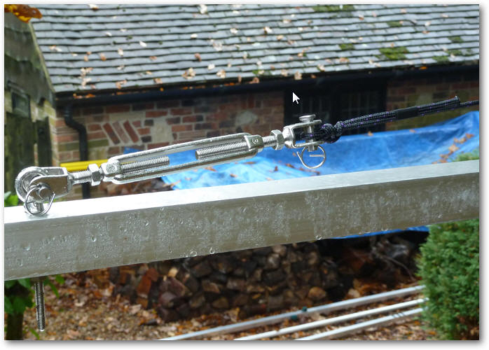
Here is one of the three turn-buckles used to level the boom.
I was not keen on feeding the two feed cables through the boom and out of the back so I will probably use the arrangement shown blow using fibreglass rod and PTFE standoffs.
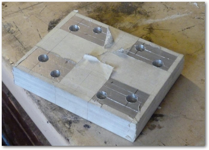
This is how I drilled the holes for the four H-frame brackets use to stop the the two antennas 'windmilling' in high winds.
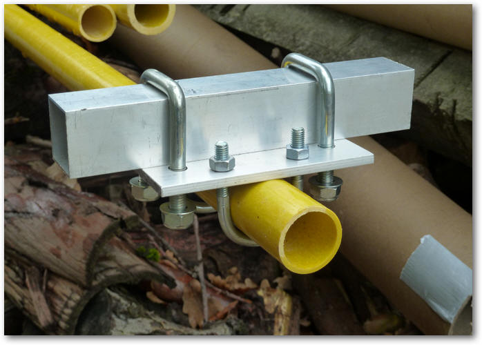
This is one of the four H-frame barckets made up.
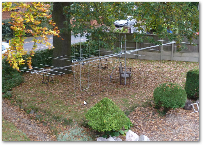
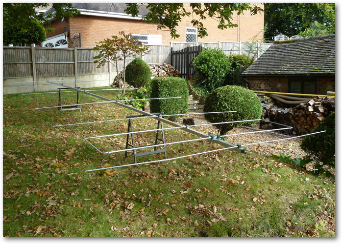
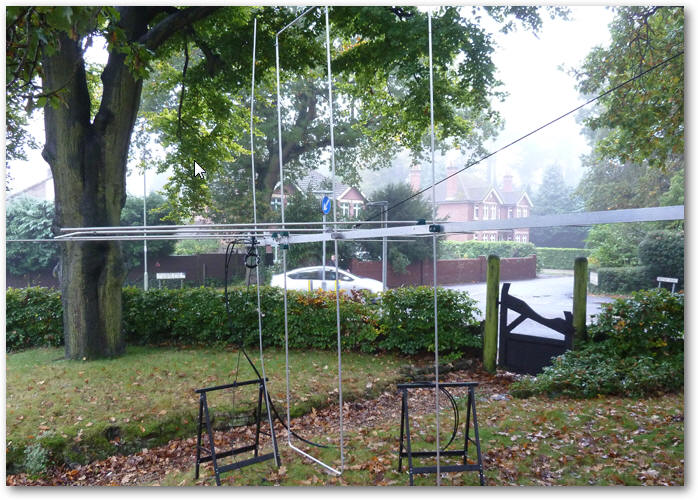
The is the first time I have assembled the whole antenna. This time round I will balance it with the 1.6kG of coax actually connected to the antenna - it make a GREAT deal of difference, especially in this case where I feed the two cables out of the back.
It seems much more difficult to get the antenna guys ropes in the correct place so that the front and the back of the antenna are level with each other as everything seems dependent on everything else weight wise. I think I have it sussed now and place the support stanchion as close to the centre of balance as possible.
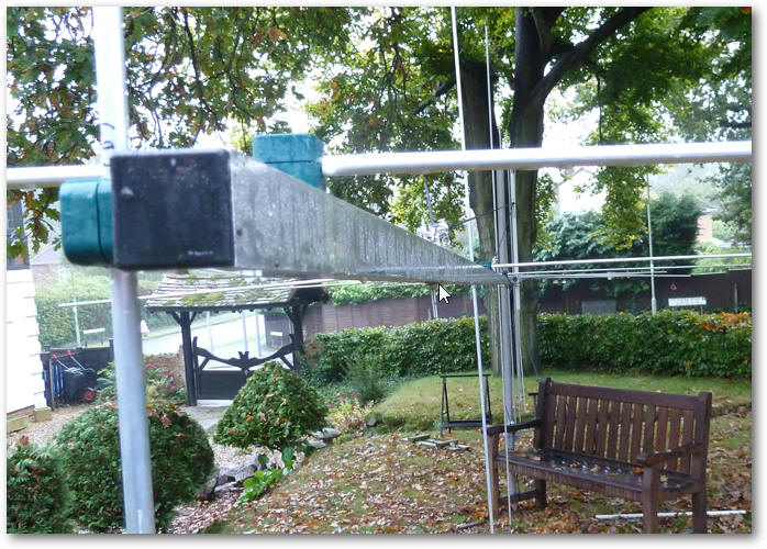
The back of the antenna looking towards the two loops.
A nice straight boom!
Being a perfectionist I did not want the boom to bend like a banana in the horizontal plane so I offset the bottom bracket of stanchion by 5mm.
The next job is sort the coax cables out.
Both antennas have now complete. I will only put the vertical elements on after I have mounted the antennas on the tower.