An alternative to the 6M7JHV antenna for 6m / 50MHz)
Making the back section of the boom
Now to make the boom assemblies.
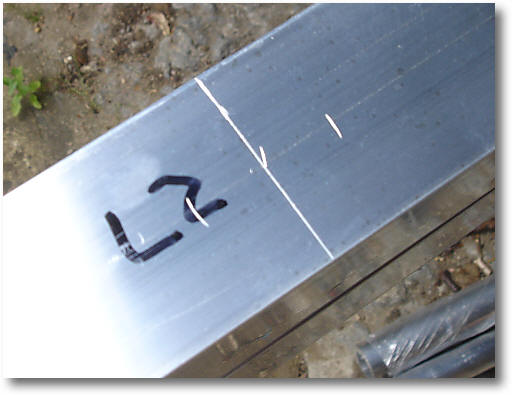
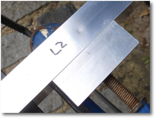
Adjust the marker gauge to the centre of the boom and mark a line down the centre of the two 5000mm 1.5" booms and the 2500mm boom support.
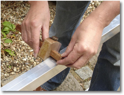
The boom centre lines
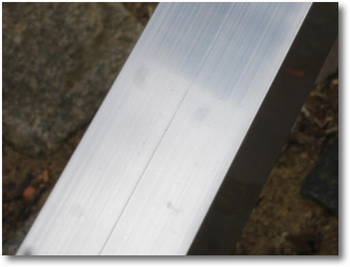
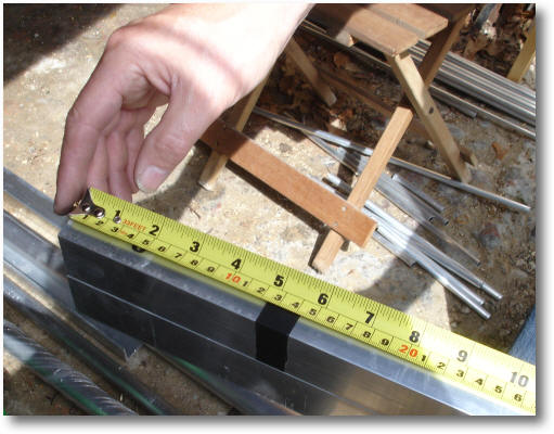
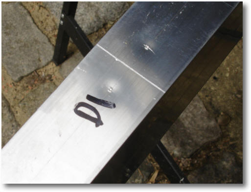
Using the 10M tape rule (with the screw in the end!), start marking the position of the elements with a scribe. MAKE SURE YOU DO THIS ACCURATELY. If you really wish to be pedantic, then you can measure the positions from both ends of the boom.
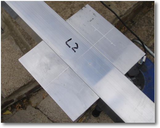
We will start with the back section of the boom i.e. the bit that contains the loop.
Marking the position of the elements
(Note: I am making 2 antennas so I'm drilling 2 booms together)
Marking the position of the elements
(Note: I am making 2 antennas so I'm drilling 2 booms together)
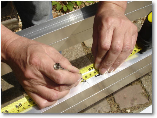
Then using a mitre square, scribe marker lines across the boom.
Marking the element positions
(Note: I am making 2 antennas so I'm drilling 2 booms together)
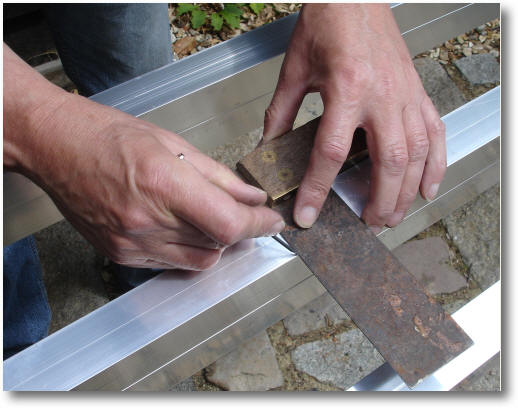
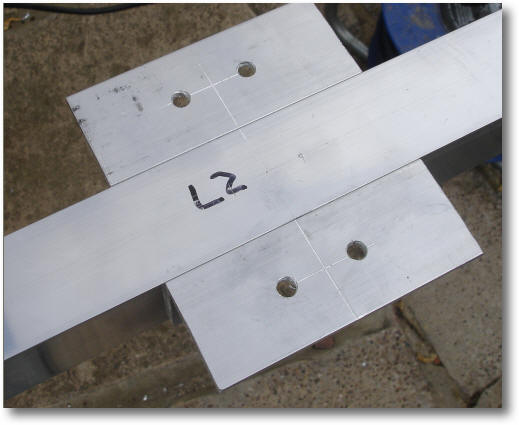
Using a pair of divider compasses set to 13mm mark the position of the two 6mm holes that will hold the Stauff element clamps to the boom. There is no need to do this for the driven element side of the loop as the clamps are mounted on brackets, not the boom.
Marking the position of the Stauff clamp holes
(Note: I am making 2 antennas so I'm drilling 2 booms together)
The position of the two holes to hold a Stauff clamp
(Note: I am making 2 antennas so I'm drilling 2 booms together)
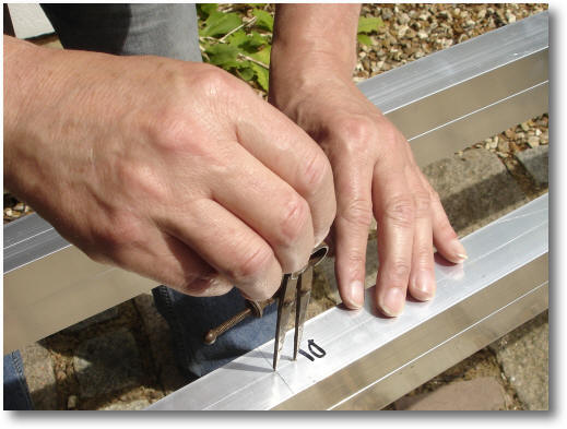
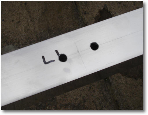
Then use a centre punch to mark the holes to avoid the drill slipping when drilling the holes with a M6 clearance drill (6.2mm).
Mark the position of the holes with a centre punch
(Note: I am making 2 antennas so I'm drilling 2 booms together)
The marked holes ready to drill
(Note: I am making 2 antennas so I'm drilling 2 booms together)
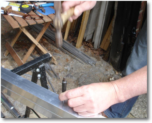
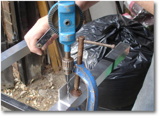
This is really a two person job as the boom sections are 5 metres long - drag in the help of the XYL! Now carefully drill the 6.2mm holes for the clamps using a bench drill.
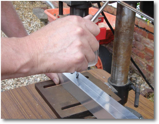
Drilling the clamp holes with a bench drill
Then de-burr the holes with a drill.
This how they should look
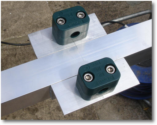
By now it's too late, but try a clamp and its bolts to check that all's well!
Tip: Always use some Vaseline on the screws before tightening them as this prevents the stainless steel screws possibly locking up!
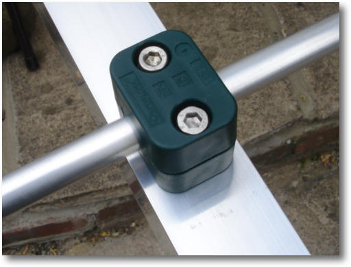
Yes, the clamp fits - phew!
The next task is to cut and drill the two brackets that support the directive element (or should that be loop?) clamps. This is made from the 1.5" x 1.5" x 1/8" aluminium angle. Cut two 100mm lengths of the angle, use a rule, marker gauge and square to position the 6mm mounting screw holes 55mm apart. Then drill and clean the four holes. These will then be mounted to the boom and marked up to drill the holes to mount the driven element.
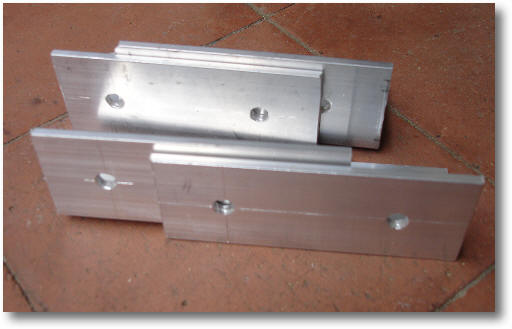
The driven element clamp mounting brackets
(Note: I am making 2 antennas, for 1 you only need 2 brackets)
Use a pencil line to mark the centre of the bracket and align this with driven element centre line i.e. the back of the loop. I used a pencil line here so that it can be rubbed off later. Notice the mistake of centre punching the boom is a place a hole was not needed? Anyway, at least I didn't drill a hole!
Use a G-clamp to hold the bracket to the boom and carefully align the bracket with the top of the boom.
Aligning the bracket
Put the M6 clearance drill in a hand drill and make a centre mark for the two holes to be drilled through the boom using the bench drill to hold the two brackets to the boom.
Marking the centre of the mounting holes
Bolt the two DE clamp brackets to the boom using M6 x 60mm screws.
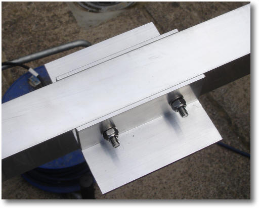
Bolting the brackets to the boom using M6 x 60mm stainless steel bolts
Carefully scribe the centre positions of the two Stauff clamps M6 mounting bolts.
Mark the positions of the clamps on the brackets
Drill the four holes.
Drill the four holes
Yes! They fit