An alternative to the 6M7JHV antenna for 6m / 50MHz
Baying the antennas
 Stacking antennas is great for DX terrestrial QSOs as it lowers the angle of main lobe from 6
degrees to 4 degrees. However, for 6M EME use it could be said that this arrangement in sub-optimal for several possible reasons:
Stacking antennas is great for DX terrestrial QSOs as it lowers the angle of main lobe from 6
degrees to 4 degrees. However, for 6M EME use it could be said that this arrangement in sub-optimal for several possible reasons:
- Lowering the main lobe could make the antenna system more susceptible to noise located locally in the main lobe.
- Lowering the main and secondary elevation lobes limits the opportunity for EME QSOs via the secondary lobes.
- It is very difficult to elevate stacked antennas.
Baying the antennas
An alternative to stacking the antennas is to bay them i.e. place them side by side. This arrangement has some particular benefits:
- Side lobes are reduced.
- Main lobe is reduced from 40 to 28 degrees.
- The bay can be elevated much more easily.
These seemed to be such good benefits I decided to have a go at this arrangement!
The pair of bayed antennas as modelled in EZNEC
Segment '53' is the 1500mm section of 2 1/4" aluminium pipe used to reinforce the fibreglass cross boom - even this length affects the bayed antenna's pattern!
There is a trade off between side lobe size / forward gain and front-to-back ratio - reducing the spacing further reduces the side lobes but also reduces the f/b ration and forward gain. The trade off is shown in the table below.
| Spacing (Metres) | Forward Free Space Gain (dB) |
Front/back (dB) | Approx front side lobes (dB) |
| 4.5 | 14.76 | 24.65 | -30 |
| 5.0 | 14.98 | 25.24 | -29 |
| 5.5 | 15.18 | 25.96 | -25 |
This is an EZNEC model for two bayed LFAs spaced at 5.0 metre spacing - I plan to use a 5.5 metre spacing.
5-metre spaced bayed LFAs - azimuth plot
5-metre spaced bayed LFAs - elevation plot
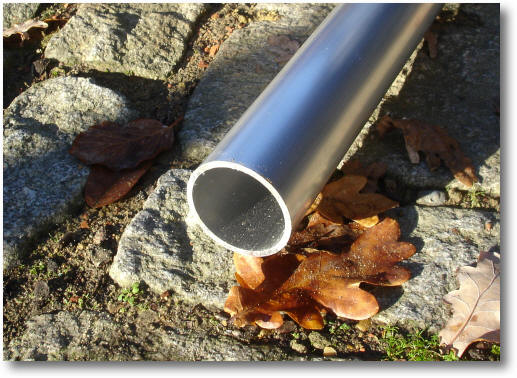
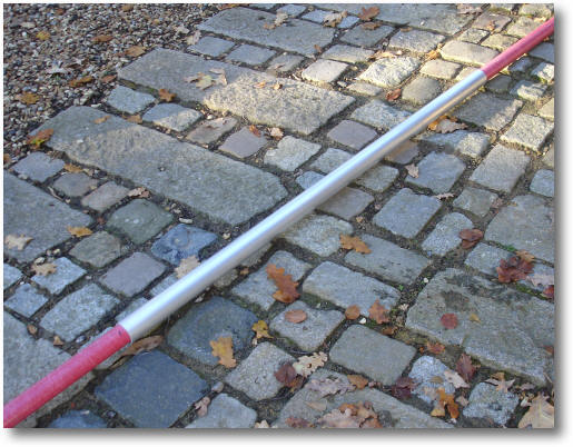
This is the 6 metre length of reinforced fibreglass tube used to support the two bayed antennas available from Engineered Composites in the UK.
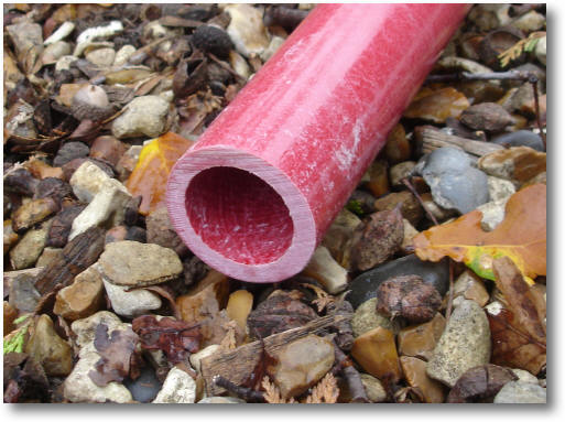
Fibreglass scaffold pole
The antenna support stanchion is made from 1 meter of 1 1/8" by 10 gauge aluminium tube.
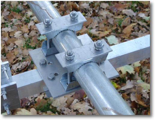
The antenna support stanchion bracket
The bracket is made from 5mm aluminium sheet with two 35mm stainless steel u-bolts.
The antenna support stanchion bracket
I decided that the previously used turnbuckles were a little on the weak side so I've used 8mm stainless steel ones bought from Ebay.
The antenna support stanchion bracket after
tightening the rope.
I used the brackets build previously but have not drilled holes in the boom this time so the bracket can be moved along the boom to perfectly balance the antennas. Note: the aluminium boom shown was only used to balance the antenna on the ground.
The antenna support brackets.
I've used 8mm turnbuckles which are much more robust than those previously used.
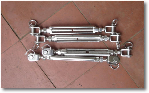
The 8mm turnbuckles.
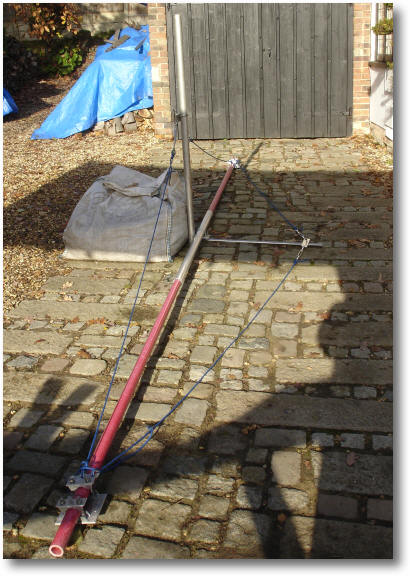
Everything seems to fit to together...
I'm just awaiting the elevation rotator and to fit the cross support brackets.
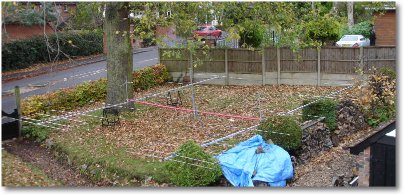
The bayed antennas laid out on the ground.
The 1.5 metre of 2 1/4" by 10 gauge tubing that fits over the centre of the cross boom to add strength. Lengths of greater than 1.5 metres interfered with the antenna pattern excessively.
The 2 1/4" by 10 gauge boom strengthener
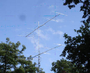
I've always had problems with a large tree interfering with the rotation of my stack - it would be even worse for a bayed arrangement so there is little choice but to cut it down. Several trees in my garden have protection orders on the them but as this was only an acacia tree there was no problem.
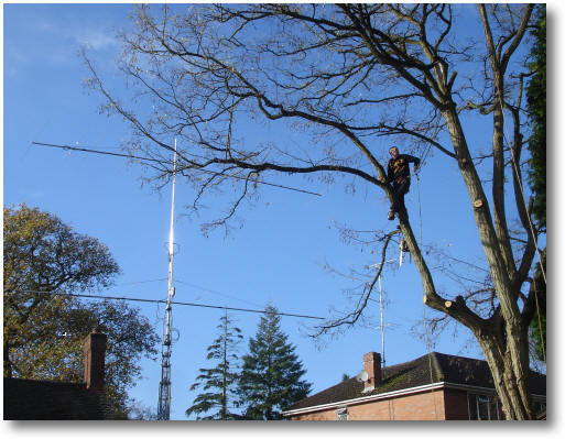
Cutting down a large 50-year old tree to make room for the bay
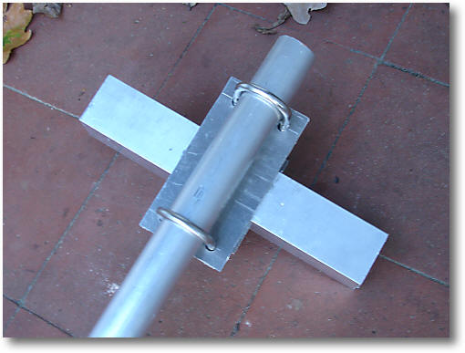
The tube just slides over the fibreglass scaffold pole and will be attached by four M6 screws through the boom.
The aluminium tube on the cross boom.
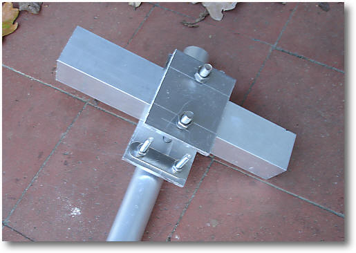
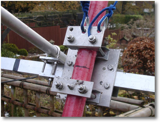
I've modified the antenna mounting brackets by adding a support mounting plate that incorporates 'eyelets' to prevent the support rope chaffing.
I've also added an M6 bolt that goes through the boom to prevent the antennas windmilling in windy weather.
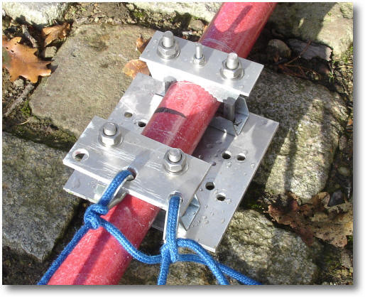
The modified mounting brackets
At a suggestion from G4CCZ, I have used a few turns of insulation tape to take up the small space between the fibreglass boom and the 2 1/4" aluminium pipe.
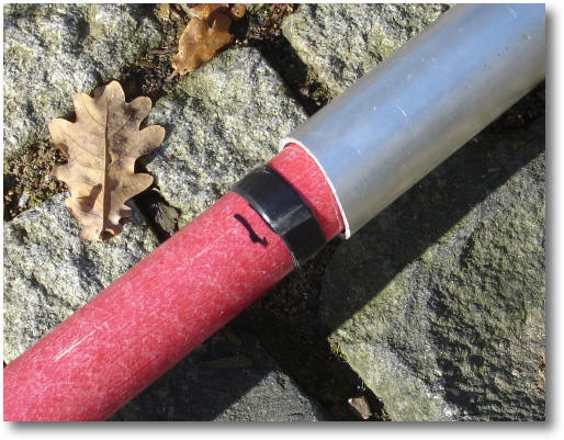
Wraps of insulation tape
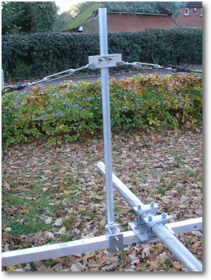
The top and front rope supports and brackets are now all complete and ready to assemble! If I really need to, I can put support ropes at the bottom and back of the boom as well - but I'm sure I will not need them. The front support is required to prevent the antennas splaying when highly elevated.
The top and front supports completed.
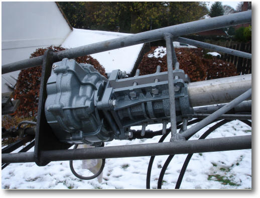
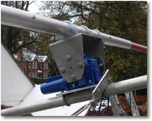
The Prosistel elevation rotator I plan to use is available from Vine Communications and what a beast it is!
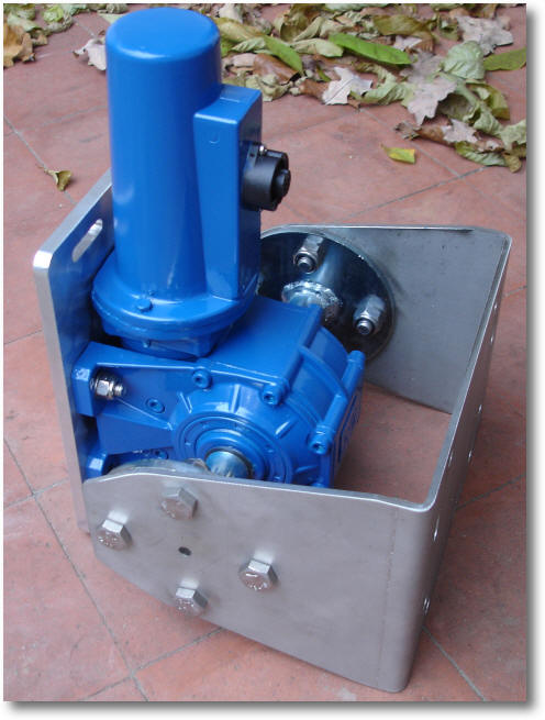
The Prosistel elevation rotator
I used 60mm x M8 u-bolts to mount the cross boom on the elevation rotator.
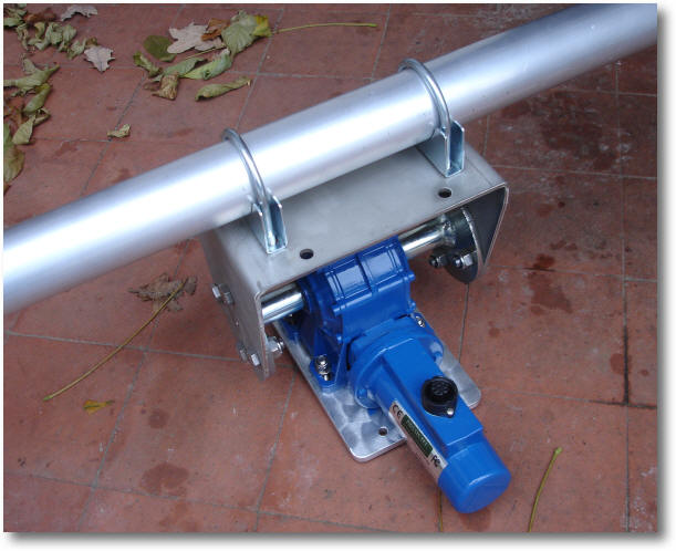
Mounting the cross boom on the elevation rotator
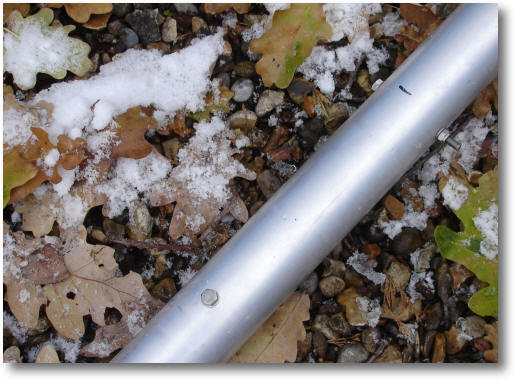
Four bolts to prevent the fibreglass boom from rotating inside the support tube
The create RC5A-3 rotator
The Prosistel elevation rotator mounted
Mounting the cross boom
The antenna brackets in situ
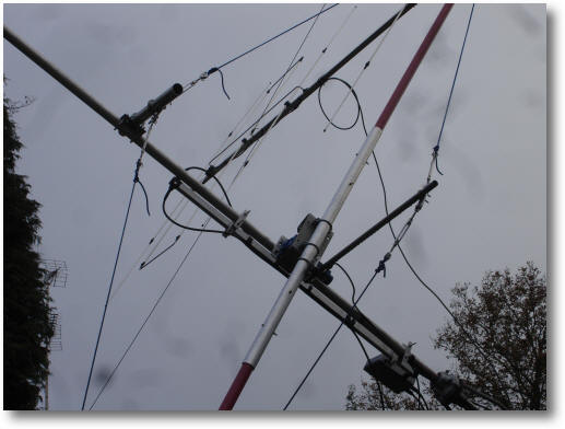
The antenna supports
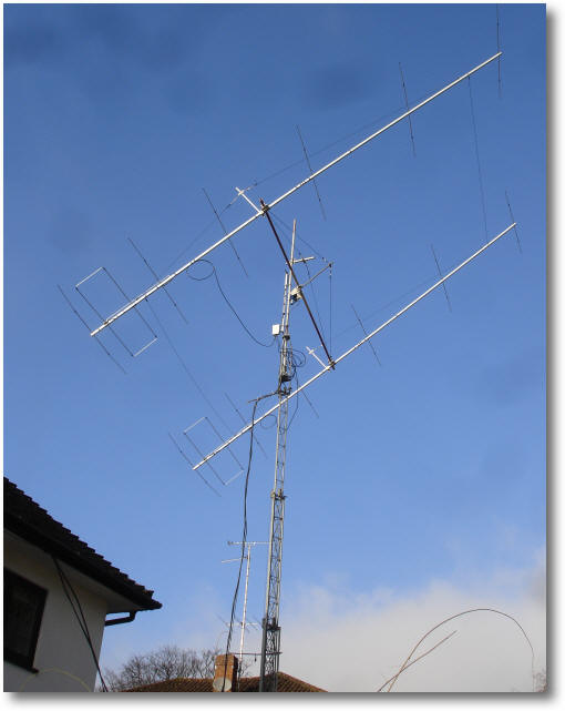
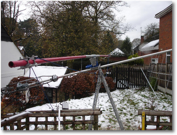
Finished and elevated to 40 degrees!
Noise reduction.
One the main reasons for adding the ability of elevation is to enable me to reduce the impact of local noise sources which has a dramatic impact on JT65 and other QSOs. My worse direction is 90 degrees. The image below is shows a background noise level of +7dB higher than my quietest heading of 50 degrees.
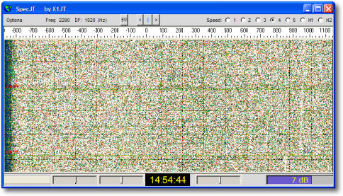
The antennas pointing at the horizon
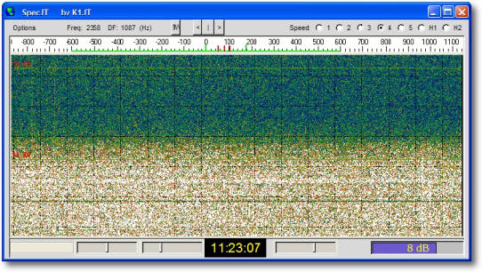
If I elevate the antennas to 35 degrees the background noise level drops dramatically to 0dB. Of course, this level of elevation will only be usable with EME but I can now reduce local noise by elevating by only a few degrees which will be useful for certain terrestrial QSOs.
The following images were taken using a 2.4kHz filer width - the S-meter was not moving with the antenna at 0 degrees on the horizon.
The antennas elevating from 0 to 50 degrees
When I added elevation I can see noise reductions of 10dB plus! Note that by elevating by only 15 degrees reduces background noise by 2dB - that is a lot! Once elevation reaches 30 degrees then the sky 'noise floor' has been reached. In practice this means that I am able to see all the JT65A traces of stations I have worked via EME.
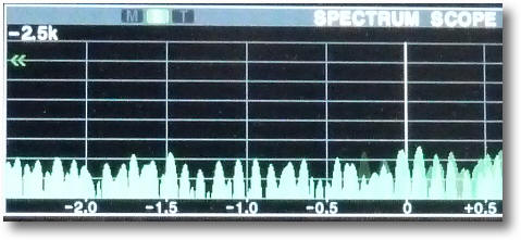
Background noise at 0 degrees (10dB/division)
The antennas elevating from 0 to 50 degrees
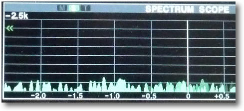
Background noise at 50 degrees (10dB/division)
Benefits of Elevation as seen by others